 |
 |
 |
|||||||||||
|
||||||||||||
 |
 |
|
Modifying Motorola pagers to use as dedicated receivers (And why I wrote my own POCSAG decoder)
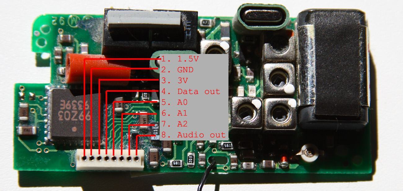
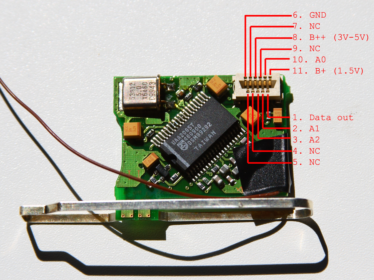
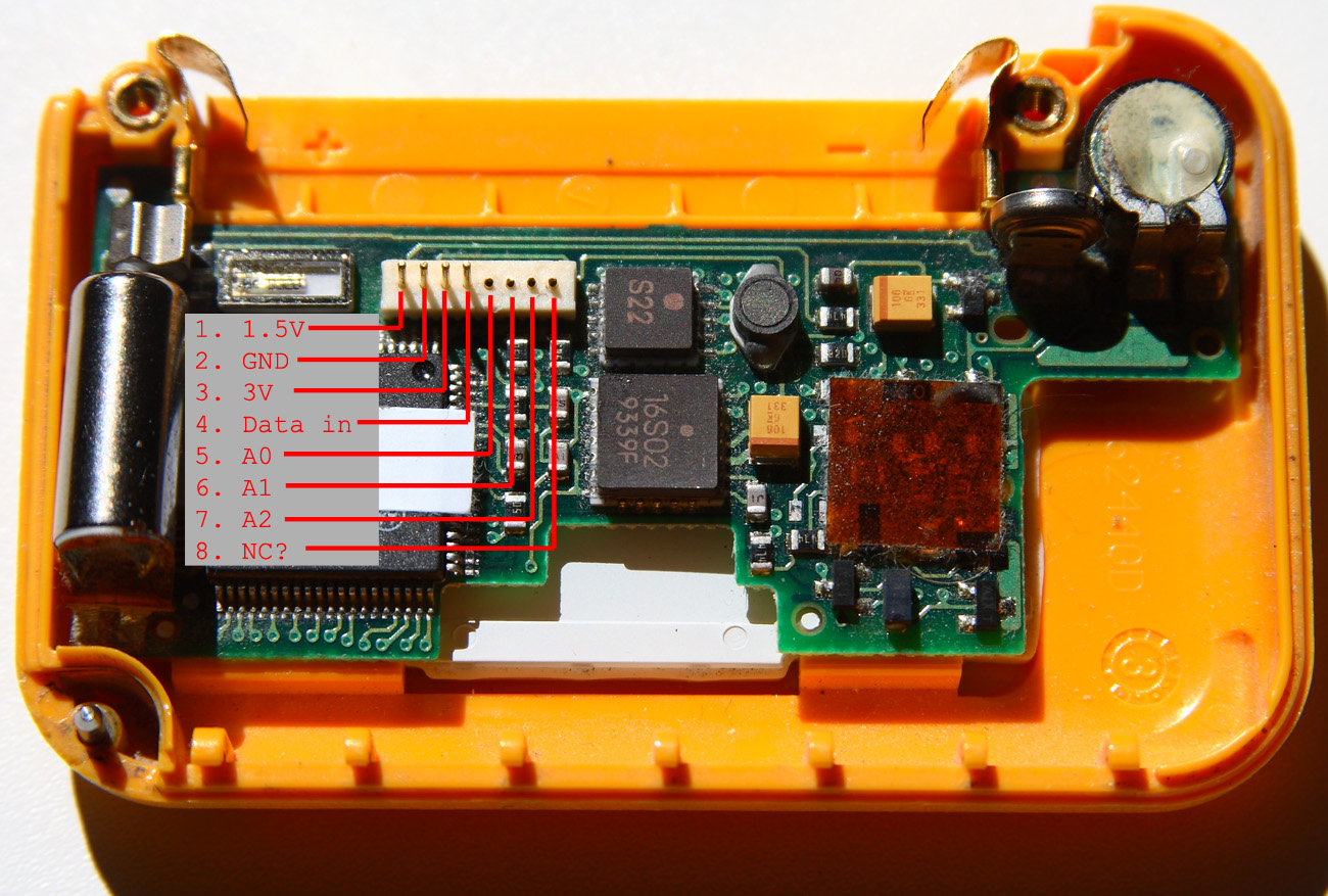
I have been doing sporadic POCSAG decoding with POC32 since the year 2000 when I got my Icom IC-R10; at most a few days at a time. I have been wanting a permanent logging solution but there are two nationwide POCSAG frequencies in Sweden and at the time I only had one receiver and only one computer on which I could run POC32. I've been running a Linux server a few years now and it seemed like a good idea to utilize that box for POCSAG decoding instead of tying up my workstation doing it. However, there is no usable POCSAG decoder for that platform. Yes, I tried multimon, but there are several problems with it. First of all, it is very plain in its feature set. Secondly, it requires access to X windows. If you start it from a non-X terminal it won't complain about the lack of access to X windows but rather it'll just go ahead and kill every process that it can. This is usually pretty annoying if you're running it as root and you are remotely logged in to the box, because it means either rebooting the box or logging in on the console to restart all the services that were killed. In January 2008, annoyed at the fact that there were still no working POCSAG decoders for Linux, I wrote my own. I'd never written anything quite that large before (the closest thing would be my POCSAG encoder which I wrote in pascal in 2002). I also got to include all the features I wanted that nobody would ever have thought to include :). I left this program running for a few months with my IC-R10. But I wanted more than that. I had read that it was possible to modify pagers to use as dedicated receivers for the purpose of decoding POCSAG (or FLEX, or Golay, or whichever pager protocol you might prefer.) So after doing some research, I picked up two used Motorola pagers; a Bravo Express and an Advisor II. One for each frequency. (Bravo Express: 169.8 MHz, Advisor II: 161.4375 MHz) Because the information I found on the subject of modifying Motorola pagers really wasn't that thorough, I decided to put together this document detailing my experience modifying them in the hopes that it will help someone trying to accomplish the same thing. Motorola Bravo Express This pager consists of two boards that are interconnected with 8 pins (click to enlarge):
I quote here part of a schematic I found (full text here):
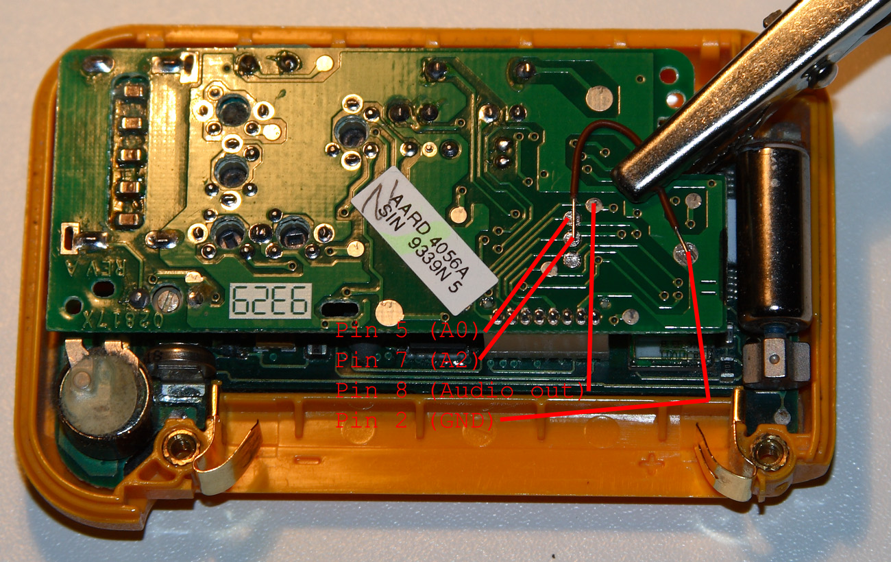
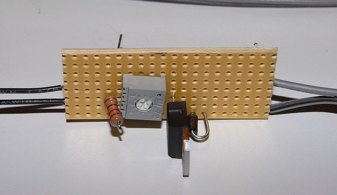
While it doesn't say in this particular schematic, pins 5, 6 and 7 are control pins and they are apparently known as A0, A1 and A2, respectively. The output from pin 4 is the received signal processed through a comparator. In normal operation the CPU board will trigger the radio board by grounding pins 5-7 at regular intervals. If you listen to it, you'll hear short bursts of square wave shaped noise, with the occasional bursts of POCSAG. My original plan was to use the radio board standalone. I tried hooking it up according to the schematic above. But it didn't work. I tried modifying it slightly, by varying the resistance and also by connecting a capacitor at different points in the circuit. The sound I got out of it was not usable. Here's what it sounded like: After tweaking the curcuit (changing resistors, adding capacitors), I got a slight improvement, but it was still far from being usable. While testing this out I was monitoring the output of the radio board with the line-in port on my soundcard. My guess is that pin 4 on the radio board is very sensitive to impedance mismatches. (Somebody please correct me if I'm wrong, I'm still curious as to why it didn't work.) Although pin 8 is marked as unused, I was happy to find that it provided an unfiltered audio tap; basically like what you get from a discriminator tap on a scanner. This output didn't appear to have the same impedance mismatch sensitivity. At this point I figured that rather than running the radio board standalone, it would be better to just modify the pager case with external connectors and bridge pins 5-7 to ground. Here's the solder side of the radio board with a piece of jumper wire positioned prior to soldering (click to enlarge):
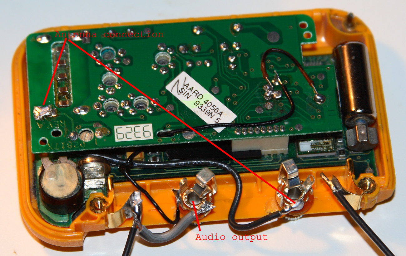
Here's what it looked like after grounding the control pins and attaching jacks (click to enlarge):
I only grounded two of the control pins. That's all that was needed. (Although if you're able to tap the output from pin 4, it might be wise to ground all three of them. Read below about my findings with the Advisor II.) If you look at the top picture in this section, you'll see that I cut 4 of the pins. After grounding the control pins on the radio board, the CPU board does not operate. I.e, the LCD doesn't come on. My idea was to allow the CPU board to run, although for my purposes it didn't really matter. It was more for aesthetic purposes. The piece of electrical tape I put over the pins for insulation didn't hold up anyway. The radio board operates regardless. Not so with the Motorola Advisor II however, where you really need to disable the control pins (see below). Note the antenna connection. While pager signals generally are strong, pagers work best when attached to your body. Because I was not planning on keeping it on my person I needed the ability to attach an external antenna. Also, I had planned to mount three jacks on each of them, but I ordered the wrong combination of dc jacks and plugs, and being that I was eager to get this completed as fast as possible, I just soldered the power supply wires directly to the battery terminals. Motorola Advisor II
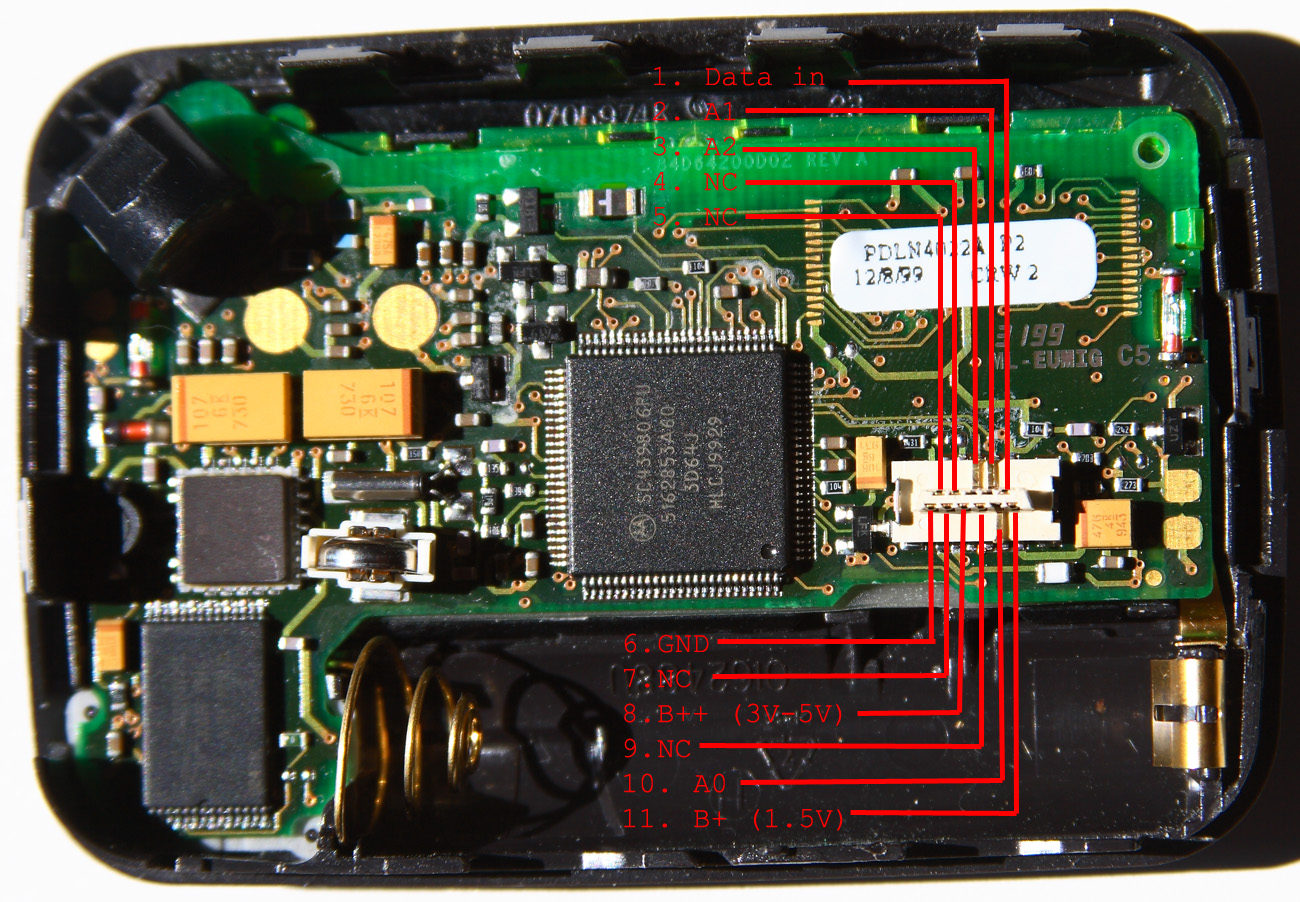
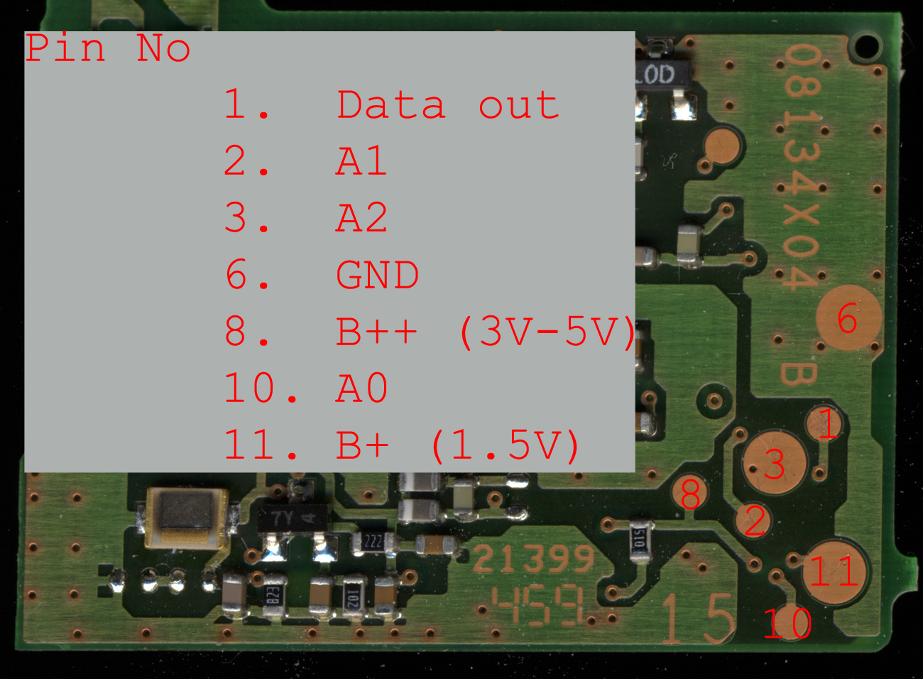
This one turned out to be a little more difficult to modify. First of all, figuring out how to get the thing open was the first hurdle. There are no screws on it. Instead the two halves are held together with a plastic band with notches on it. I believe I used a screwdriver to gently pry it off. Secondly, the radio board is very small, measuring only 25x35 mm. Inside, we find two boards (again) but these two are interconnected with 11 pins, of which 7 are used. Here's the pinout:
It says LX2, but it appears that the Advisor II uses the same radio board as the Scriptor LX2 and LX4. This russian schematic appears to suggest that in order to use the board as a receiver, you need to wire it according text in the top right corner. Specifically, it states you need to ground pins 3 and 10, and supply 3V to pin 2, which are control pins A2, A0 and A1, respectively. Looking at the table, we see that the item "TRACK 600hz filter" applies to this configuration. Apparently this means that the radio board will filter the signal before sending it through the comparator. When I attempted decoding with this configuration, the error rate was unacceptably high. Instead, when I grounded all of the control pins; 2 (A1), 3 (A2), 10 (A0), filtering was disabled and the decoding results were fine.
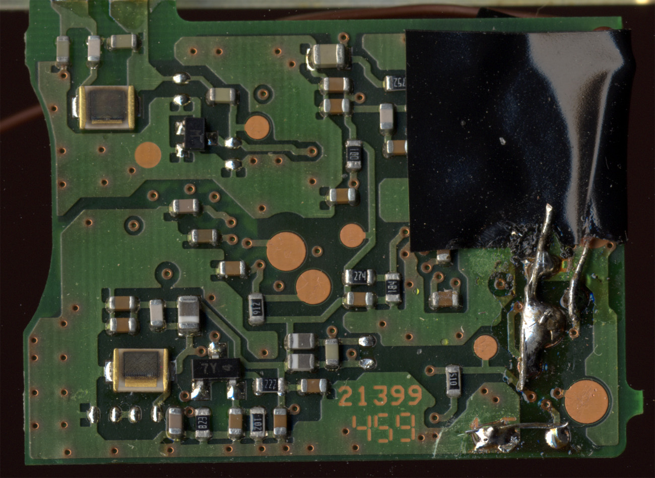
Here's what the backside of the radio board looks like. The most important pad (pin 1) is also one of the smallest ones (~1.4mm) and it's located right next to a larger pad (control pin A2) that needs to be grounded. Be careful when soldering.
And here's what it looked like after soldering:
After performing this modification, you will need to disable the control pins, or else the pager won't power on. I used a loupe and a sewing needle.
And after attaching jacks:
I put in an antenna jack in this one also. I had to remove some of the plastic on the inside of the cover to make it fit. The casingI wanted to put both of these pagers in a box, preferably a transparent one. Luckily I stumbled across a plastic case from a Velleman electronics kit, which was just what I needed. To this I added jacks for power, sound and antenna. The power supplyI also wanted to be able to power them from a PC, so I built an LM317-based voltage regulator from this schematic (minus the capacitors):
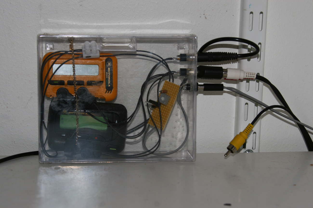
This one connects to a USB port with a custom cable. The finished product
The current position as it sits in my storage room feeding the decoder running on my Linux box. Each pager feeds one channel of the line-in port. I've connected up an old pair of headphones for use as an antenna. Here's a short stereo recording of what it sounds like. The Bravo Express (yellow) is on the left channel. This modification project was done in June of 2008. I created this page in late 2008. As of this update (October 2011) I've been using this setup for a little more than 3 years and it's still working great. The only problems I've had that caused decoding errors were due to external factors:
My POCSAG decoder As hinted at the top of the page, I wrote my own POCSAG decoder. It currently consists of about 1500 lines of Perl and 300 lines of C. The C code exists in the form of an XS module which does most of the heavy lifting (scanning/parsing PCM data). It features:
I am not actively developing this version anymore, because it does what I want. I have not decided whether to release it publicly yet. It needs work, mainly on the user interface part. I am slowly working on rewriting it to pure C, and when I finish that I will probably put it here or on sourceforge or something. However, I am mentioning this here because there is probably somebody out there who is looking for a POCSAG decoder that runs on Linux. Drop me a line if you want to try it. January 2012: The C POCSAG decoder is nearly finished. The code is very stable and all the major features have been implemented. The remaining work consists of some minor code polishing, finishing the documentation and creating a configure script and Makefile for convenient compilation and installation. I expect to have it finished mid-to-late 2012. June 2012: The C POCSAG decoder is now finished. Click here to try it out. April 2026: Except for a "pause" (*) during May 2020 - July 2023, the motorola pagers described on this page have now been running for 18 years straight and they're still working fine for POCSAG decoding. YAY |
|||